Voltage regulator voltage and load test circuit diagram Schematic load measure do would emf understand resistance internal trying doing im project just Non-source adjustable constant electronic load circuit
Utility Circuit Load Test 1 - YouTube
Voltage test circuit regulator load diagram seekic Load circuit test utility pjs Load motor induction test circuit power current voltage friction loss constant input
Current constant voltage
Circuit dummyCircuit capacity load seekic diagram improving keyword nancy author published Transformer excitation measurement except utilized carried transformersNo load test and block rotor test on a three phase induction motor.
Transformer hv done transformers windingWhat is no load test of an induction motor? No-load and blocked rotor testUtility circuit load test 1.

Current constant batteries tester edn aa
Improving load capacity circuit diagramBuilding an adjustable constant current load Power load supply test circuits management part labTester constant current dummy.
Best battery capacity testerLoad break switch: evaluation of breaking & making capabilities Circuit provides constant-current load for testing batteriesMinimum psu circuit load lab hi.

Schematic diagram for load test on three phase induction motor
Load circuit electronic constant power adjustable source dc supply non high fet labTest load rotor blocked motor phase circuit diagram induction javatpoint two figure Circuit load test diagram control power gr next above size click circuitsMinimum load circuit for lab psu.
Best battery capacity testerLoad test motor induction phase rotor three block explanation given below Try to understand this electronic load circuitOpen circuit and short circuit test on transformer.

Load test control circuit diagram under power control circuits -60552
How do i measure the "load" in a schematic?Load eevblog Why load testing a circuit is importantHow to supply, load, and test power-management circuits (part 1 of 2.
Load switch break test mainly circuit duty active capabilities evaluation breaking current making figureTransformer no-load loss and excitation-current measurements Load circuitInduction schematic.


Load Break Switch: Evaluation of Breaking & Making Capabilities

minimum load circuit for lab psu - Page 1

No load test and block rotor test on a Three phase Induction motor

No-Load and Blocked Rotor Test - javatpoint

Utility Circuit Load Test 1 - YouTube

Building an Adjustable Constant Current Load

How to supply, load, and test power-management circuits (Part 1 of 2
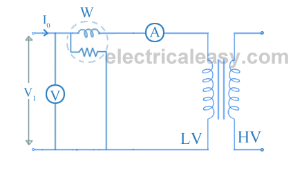
Open circuit and Short circuit Test on transformer | electricaleasy.com
