#electrical_circuits_analysis || examples the locus diagram of parallel Locus diagram Locus diagram (part 2)
Induction Motor: Reason why the current locus is on the positive
Impedance locus and the electrical equivalent circuit of an Impedance locus equivalent electrolyte electrode interface Induction motor: reason why the current locus is on the positive
Admittance locus diagram for series rlc circuit
Locus diagram of series r-l and r-c circuitsIn the locus diagrams of two projectiles 1 and 2 as shown in the fig Locus diagramRoot locus plot detailed explanation.
Root-locus diagram for the design of pi controller. (a) t > . (b) tLocus series diagram Locus current induction imaginary reason motor why axis positiveTypes of locus holding-electrical engineering-handout.

Locus diagram in network theory
.
.

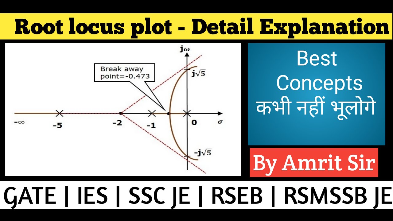
Root Locus Plot Detailed explanation | Solved with Example | Diagram

Locus Diagram of series R-L and R-C Circuits - YouTube

Types of Locus Holding-Electrical Engineering-Handout - Docsity

Induction Motor: Reason why the current locus is on the positive

locus diagram in network theory | locus diagram of rl and rc circuit

Locus - Diagram, Equation, Solved Problem - YouTube

#Electrical_Circuits_Analysis || Examples the Locus Diagram of Parallel

Locus Diagram (Part 2) - YouTube

Admittance Locus Diagram for Series RLC Circuit | Locus Diagram

Locus Diagram | Electrical Impedance | Physical Quantities
